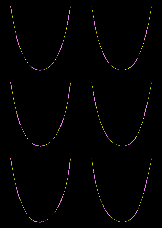

The upper short blue arrow indicates the location and magnitude of the combined sling loads. The upper red arrow indicates the location and magnitude of the combined added buoyancy force. The central purple arrow, pointing down, indicates the location and magnitude of the combined weight force. The lower brown arrow indicates the location and magnitude of FG, the ground reaction force. The variable Tpivot, is the transverse distance of FG from the keel. At this distance, FG causes a moment that balances the system such that there is no net heeling moment. Labels indicate vessel frame numbers. Each frame identified is drawn with a different line color in the Excel chart. The frames are shown with the vessel trimmed. Hence Frame 173, in the region where the bow slings attach, appears raised. Frames 0, 6 and 6 are indicated and can be seen to be without any significant seabed contact. The following properties are derived by the line type wizard: click on the link for details of the calculation of each of these values.Heel Equilibrium Solution During Bow Lift In subsequent topics, we define the base line type notation, that of the underlying line onto which the floats are to be attached, and the notation for the floats themselves. The values generated by the wizard are based on current best practice, but more specific project data should be used where this is available. Note that this approach is also suitable for modelling a regularly weighted section of line: 'floats' are not required by OrcaFlex to have positive buoyancy. It will automatically derive the data for the new line type, based on those of the original line and the floats. Step 2 is performed by the line type wizard. uniformly over the length of line from $s_\mathrm3$.

This is done by spreading each float's buoyancy, drag, etc.

This smeared properties approach involves the following steps: This allows the length and segmentation of the buoyed section to be varied easily without having to add and remove individual floats. spread out evenly, along that part of the line. However when a number of floats are supporting a length of line it is often easier to model the buoyancy as if it were smeared, i.e. You can model floats or buoyancy modules attached to a line with discrete buoyant clumps attached at the relevant points.


 0 kommentar(er)
